Perform large scale airborne LiDAR strip alignment faster and more accurately than existing software using advanced, fully automatic algorithms. No need to preprocess, classify or filter the data. Also works with most UAV scanners and some Sonar point clouds.
Input
– LAS/LAZ 1.4 or ASCII separate flight lines, projected
– SBET/SOL/TRJ/POF/BIN/ASCII position & orientation, projected or geodetic
– [PulseWaves files PLS/PLZ with related swaths]
– [GCP file] [parameters] [option file]
Output
– Corrected LAS/LAZ strips [PLS/PLZ] or tiles
– QC maps, images, stats, logs, reports
– Updated PO and corrections
Fast point cloud registration compared to ICP or feature matching
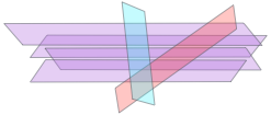
No flight line geometry restrictions, use all swath overlaps
No classification needed: robust to vegetation, viewpoint, changes, noise
Effective relative accuracy improvement AND minimal absolute error
Integrated boresight, lever arm and internal geometry calibration
Auto. high frequency trajectory/attitude drift corrections
Auto. sensor calibration option without correction
Multi-channel capability for scanners such as Riegl *1560, dual VUX
Large-scale and complex projects: use groups and reference strips
Blend feature to fix edge distortions
Support for corridor mapping with limited overlap
Useful LiDAR and PO files scanning module
Fast QC with GCP, user friendly reports
Support for XYZ GCP to constrain horizontal accuracy
3D error analysis, vector images, stats
Z-differences, point density, hill shade, roughness, elevation maps
Corrects PulseWaves geometry as well if provided with LAS data
Auto merge/cut flight lines using trajectory and time gaps
Option for direct tiled output
Trajectory-free correction option
Easy to read QC reports
XML-like option file input
Improved support for UAV LiDAR
Improved support for Sonar
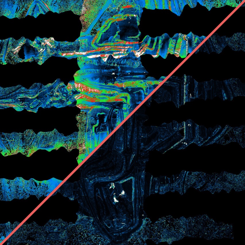
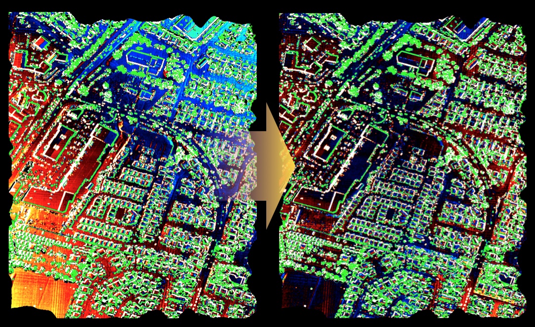
LiDAR swath alignment. Vertical difference between overlapping strips. Left: original data. Right: geometric corrections applied (high frequency drifts, calibration). The point cloud registration is robust to vegetation, mismatched surfaces and natural differences between points of view. Optimal corrections are computed automatically from relative displacements using a rigorous model and Bayesian inference.
Your benefits
Accuracy improvement
Correcting systematic errors or biases by treating them as parameters and applying Bayesian inference is a powerful way to improve the data accuracy. Strip adjustment is a good example of significant improvement, where both relative and absolute uncertainties can be dramatically reduced, depending on the number of strips and the amount of overlap.
Optimal data fusion, or swath combination, helps produce highest possible accuracy elevation models given the collected data. This is possible once the swaths have been properly aligned, so that most biases are eliminated.
Automation
Manually tuning essential processing parameters is no longer necessary. Grid size, number of iterations, internal parameters, that’s the algorithm’s problem, not yours!
Strip adjustment requires accurate alignment of overlapping point clouds from neighboring swaths. Probabilistic approaches provide automatic ways of computing the geometric transformation between such datasets while being robust to occlusions and noise.
Uncertainty management
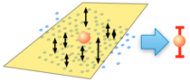
Understanding how uncertainty affects 3D points helps perform the alignment in optimal conditions, as most accurate points are given the largest weight. Uncertainty estimates do not come with the data, so we have to compute them automatically when needed.
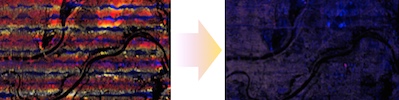
Automatic boresight calibration. Vertical differences between two overlapping cross-strips, before (left) and after (right) calibration using n strips simultaneously. A standard calibration cross, or any set of overlapping lines can be used, not necessarily parallel or perpendicular. The calibration module estimates one set of parameters (boresight angles, lever arms, 6 internal parameters) for the whole dataset. While boresight can account for a significant part of geometric errors, it is not sufficient to compensate time-dependent IMU errors, this is why we developed HF drift corrections.